Web viewer pointer controls
These controls apply to the first-party web viewer, with one model or a federation of models.
| Gesture | Action |
|---|---|
| Left drag | Orbit, except when the active tool claims the drag |
| Shift + left drag | Pan in every tool, including Measure |
| Middle drag | Pan in every tool |
| Right drag | Fly mode: look around while the button is held; use WASD and Q/E to move, and the wheel to change fly speed |
| Wheel without right drag | Zoom |
The Select tool uses Ctrl/⌘ + left drag for rectangle selection. In the Measure tool, plain left drag starts a drag measurement; Alt + left drag orbits instead. In polyline, angle, and radius measurement modes, a left drag orbits and clicks place points. Shift + left drag always pans, even when a measurement is active.
In the Model workspace, plain left movement and dragging update the active command preview without moving the camera. Placement commands commit on click; polygon placement still closes on double-click. Room shape editing grabs a corner on press, previews its movement, and commits on release as one Undo/Redo operation. A lost capture, focus loss, or command change cancels the owned room drag. A captured drag can finish outside the canvas. Shift + left, middle, and right-button navigation keep the controls above.
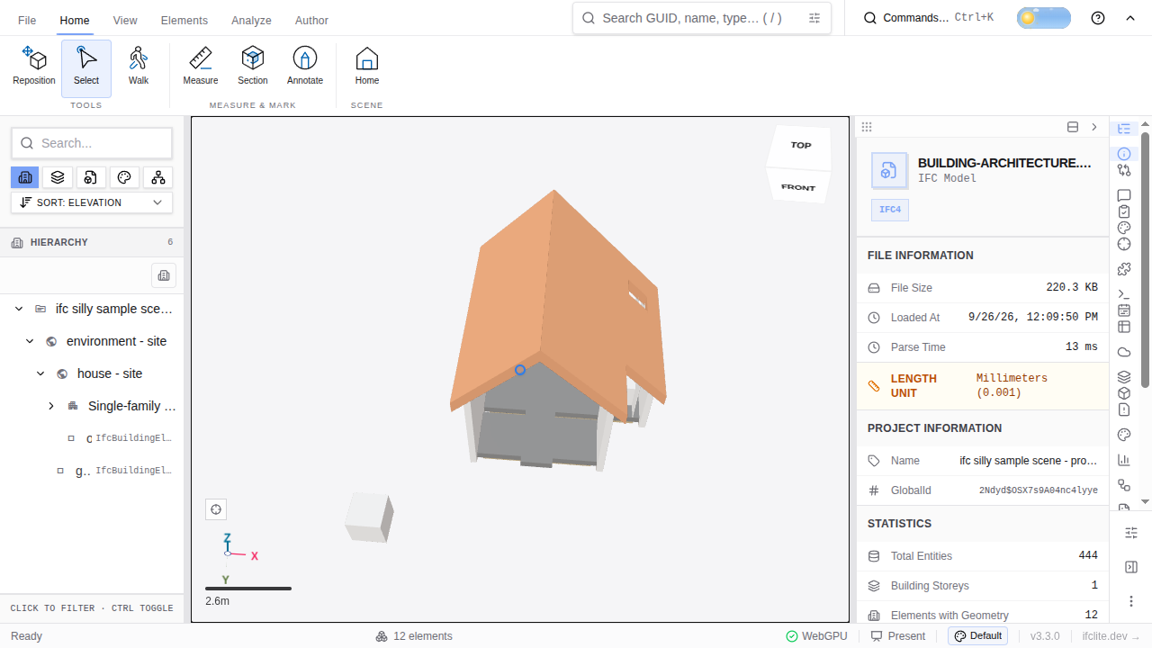
While you orbit, a small accent marker shows the fixed point the camera is rotating around. The marker follows that point on screen and fades when you release the pointer. Panning does not show a pivot marker.
An embed with camera controls disabled does not fly or navigate. Right-button fly is the viewer's established behavior (#4868); it takes priority over the ordinary right-button pan mapping used when fly is unavailable.
Navigation presets
Choose a preset in Settings → Display → Navigation. The choice is saved in this browser and applies to every loaded model.
| Preset | Pointer difference | Wheel or trackpad |
|---|---|---|
| Default | The mapping above | Vertical wheel movement zooms; horizontal movement pans |
| Navisworks-like | Shift + middle drag orbits; middle drag pans | Wheel zooms |
| Trackpad | The default pointer mapping | Two-finger scroll pans in both directions; pinch or Ctrl + wheel zooms |
Right-button fly remains available in every preset when camera controls are enabled. Shift + left drag pans in every preset and tool.
Zone volume results
Each zone-set volume report states its cached processed entity outcomes and the native proved-split and refusal counts. Whole-set runs and incremental per-element cache updates have distinct coverage; cached counts describe the evaluated boundary-crossing entities. Missing geometry, unproved solids and volumes invalidated by federation alignment retain separate reasons. Captured model names and IFC GlobalId evidence stay with older rows through later updates and panel remounts; unknown cache history shows Outcome unknown, and older native revisions show Stale. Evidence samples show their displayed and total counts. The native split, authoring, writeback and export controls remain available in their existing locations.
Alignment sections
Open Section → Alignment, select the model and its IfcAlignment, then
change Horizontal distance from start to move the cut along that axis.
The cut follows the evaluated 3D tangent, including grade and curvature.
Distance is geometric horizontal metres from the physical start; it is neither
authored chainage nor 3D arc length. Approximate supported curves are labelled.
Unresolvable units, invalid placements and unsupported curves report an error
instead of substituting a straight line.
The plane uses the selected model's frame and workspace placement. Moving that model updates the cut; pending IFC edits rebuild the selected evaluator. Removing the owner disables its bound cut. Closing the tool releases its worker and detaches the cut into an ordinary custom plane. Select the alignment again to resume station control.
Dragging the plane handle makes it an ordinary custom cut and detaches it from the alignment. Choose Alignment and select the axis again to resume station control. Flip, cut visibility, cap style, cardinal cuts, face picks and section boxes retain their ordinary behavior.
Acceptance was exercised in the production viewer with the original OIP 2017
844_terrain_and_alignment.ifc fixture (IfcAlignment #39). The distance field
moved its section through 0, 10 and 20 m; flipping the cut remained active at
20 m. An independent circular-arc calculation using the authored radius and
start heading matched the displayed horizontal station coordinates within
0.000001 m. The viewer screenshot records the rotated cut and active controls;
this check uses an original authoring-tool model, not a fabricated screenshot.
Finding a panel
The right-hand activity rail and Analyze → Browse panels in the ribbon use the same task groups. A panel can be opened from either place. Customize mode can hide or reorder rail icons; Browse panels still lists every available panel.
| Group | Use it for |
|---|---|
| Coordinate | Model hierarchy, properties, sources, zones, and placement |
| Check | Topics, validation, clashes, changes, and model comparison |
| Quantify | Measurements, lists, charts, costs, and schedules |
| Automate | Scripts, flows, and extensions |
| Site | Point clouds, appearance, environment, drawings, and presentations |
The Point Clouds panel remains available before a scan loads; it explains what to load. The Session panel appears only when collaboration is enabled.
Viewer terms
| Term | Meaning |
|---|---|
| Collection | A saved working set of selected model objects. Older guides call it a basket. |
| Session | A shared live workspace with other people. Older guides call it a room. |
| Profile | A saved viewer setup, including layout and analysis settings. Older guides call it a flavor. |
| Edge shading | Point-cloud depth enhancement. Technical settings may call it EDL (Eye-Dome Lighting). |
| Spatial index | A structure that speeds up finding nearby objects. Technical material may call it a BVH. |
| Tolerance | The permitted measurement difference in a spatial check. Technical material may call it epsilon. |
| Boundary-crossing element | An element that intersects more than one location zone. Technical material may call it a straddler. |
| Write zones to model | Create IFC IfcSpatialZone entities for the zones; older controls said “emit zones.” |
| Validation | Checking model information against rules, including IDS requirements. |
| Clash | A spatial conflict between model objects, with clearance settings when applicable. |
| Placement | The model's position and orientation, including georeferencing. |
Georeferencing rotation and scale
The model information panel's Location pin and Origin Lat/Lon show
the declared georeference origin: IfcMapConversion.Eastings and
Northings transformed from IfcProjectedCRS to WGS84. Picking or searching
for a new origin writes that position back to Eastings/Northings. The origin
does not depend on the geometry bounds, RTC rebasing, model rotation, or Scale.
For files whose geometry is already in absolute map coordinates, editing a
nearby origin can leave the footprint stationary under the existing
double-georeference correction; relocate that geometry through source placements.
If terrain elevation is available for a picked origin, applying it also sets
the model base at that sampled elevation. This derives OrthogonalHeight
using the geometry elevation; the sampled height is not copied directly to
OrthogonalHeight. The elevation label explains this behavior.
The footprint, 3D world and geometry exports also apply the element placements and map conversion. They can differ from the declared origin. A geometry centre at least 100 km from the origin raises a distance message; check the source model's placements before treating a correct origin pin as evidence that the geometry itself is correctly georeferenced.
The georeferencing field Model rotation in map coordinates is the
counterclockwise angle from map East to the model's local X-axis, viewed from
above in IFC's Z-up coordinates. Positive values rotate counterclockwise;
negative values rotate clockwise. It is derived as
atan2(XAxisOrdinate, XAxisAbscissa), converted to degrees.
IfcMapConversion.XAxisAbscissa and XAxisOrdinate store a direction vector,
rather than an angle. Its length need not be 1: (2, 2) and (1, 1) both mean
+45°. IFC-Lite uses the direction without adding scale from the vector's
length. Editing the angle writes XAxisAbscissa = cos(angle) and
XAxisOrdinate = sin(angle). An omitted Scale has an effective value of 1;
Default: 1 distinguishes that default from an explicitly authored value.
IFC map conversion definition.
When comparing with Bonsai/IfcOpenShell, check which direction the angle
describes. IfcOpenShell's grid-north convention describes the inverse rotation,
from project north to grid north, so its sign is opposite. For example,
XAxisAbscissa = 0.995644 and XAxisOrdinate = +0.093239 give approximately
+5.35° model rotation here and −5.35° under the grid-north convention.
IfcOpenShell angle convention.
To validate georeferencing, compare transformed model points with independently known survey coordinates, including units and the complete placement chain. Cancellation between a placement rotation and a map-conversion rotation is only expected when the model's original map alignment is known; it is not a general validity requirement.
Space floors and ceilings
Select a created IfcSpace, enter the Model workspace, and choose Edit space
envelope in the command palette or the Room tool's bar. Use a front view or
an active vertical section along the roof slope. Choose Flat, Sloped,
or Pitched for the ceiling. Click a floor, eave, or ridge handle, move it
to a roof edge or vertex, and click again to apply the snapped elevation.
Eaves move vertically; a pitched ridge can also move between the eaves.
Alt suspends snapping. You can also type the storey-local floor, eave, and
ridge elevations in metres and press Enter. Escape cancels the edit.
Each applied envelope is one Undo/Redo operation. It keeps the space's
GlobalId, name, properties, surface styles and spatial aggregation. The exported IFC contains planar clipping solids, so sloped and
pitched ceilings survive saving and reopening. Floor areas stay unchanged;
Height is retained only for constant-height spaces, as required by IFC.
Gross and net volumes are updated only when their source floor areas and
volumes identify the edited body; otherwise those quantities are cleared.
Ceiling, wall and finish quantities that require construction boundaries are
also cleared, so an edit does not leave stale measurements.
Editable sources are upward vertical rectangle or simple polyline extrusions
with at most 256 footprint vertices, directly placed on their storey, plus
supported envelopes previously saved by this tool. Mapped bodies, mesh bodies,
profiles with holes, tilted extrusions, extra placement parents, explicit
quantity units, and unreadable geometry refuse before writing. Horizontal,
tilted, and box sections cannot be used for this edit. A source model that was
reprojected into another CRS is also refused.
Spaces carrying ElevationWithFlooring allow ceiling edits, but refuse floor
moves until the building elevation frame can be resolved.
Selection quantity results
Open Measurements → Qty to read quantities for the selected elements. The results header identifies the selected models and population. Authored IFC quantity rows, proved enclosed volumes and triangulated mesh areas keep their separate bases and display units; the source inspection remains in the evidence region.
Coverage reports unavailable model data, unproved or alignment-invalidated volumes, missing or incomplete mesh areas and withheld derived mass. A usable mesh area remains visible when the model's quantity tables or volume proof are unavailable. Empty selection asks for elements; selected elements with no usable measurements report Partial. Finite zero-valued measurements remain results.
Autodesk cloud sources
Open Cloud sources from Coordinate mode and select Autodesk Forma / Data Exchange. The viewer administrator configures either a public APS application ID for static sign-in or a same-origin hosted session service. Hosted mode keeps Autodesk tokens on the server. Static mode keeps tokens in memory and requires sign-in after a reload. A cancelled sign-in cannot complete the pending transaction.
Browse account projects and choose Forma Data Management files or Data Exchanges. For Forma Site Design, paste a Forma site link in the project entry. IFC, IFCX/IFC5 and GLB files download through the normal loader, pinned to the listed revision. Unsupported resources show an explanation. Cancel download stops the active batch; completed models remain loaded.
The hosted service includes a Rust Forma proposal importer and a Windows Autodesk SDK Data Exchange exporter. Enable them with absolute executable paths in the service configuration. The details panel offers file/proposal version selection; whole-exchange IFC export supports the current version only. Generated resources remain disabled when their native importer is not configured. Configuration, deployment limits, current capabilities and the live-account verification checklist are in Autodesk source setup and the session service guide.
Deviation result sources and coverage
The BIM ↔ scan deviation result identifies the scan assets represented by its held distance readback. Its population counts scan points, with finite measured points shown separately from unmeasured and compute-limit-clipped points. The native summary, tolerance band, colour range, histogram and CSV retain their existing behavior. Source evidence lists captured scan GlobalIds and classes; loaded IFC models are not presented as scan sources.
Incomplete point measurements or unavailable scan identity show Partial. A summary without recorded source provenance shows Outcome unknown. Missing readback statistics show Running while they are derived. No finite measured distances produce a partial readback state, rather than claiming no findings or an absent scan population. Captured source identity remains attached through native tolerance recounts and panel remounts.
Layout migration and saved-artifact links
When an older saved layout is upgraded, Review your updated layout lists renamed, added and unavailable panels. Show changes keeps that list scrollable so Keep layout and Reset layout remain reachable. Keep acknowledges the migrated layout; Reset uses the workspace's normal reset. Both retain unavailable extension placements, their anchors and hidden state, and the original stored layout in a local rollback backup. Importing a legacy layout also backs up the current layout before replacing it. If that backup cannot be written, the original stored layout is not overwritten. These controls are available on desktop and mobile.
Older builds can read the common mode, width, order and hidden fields. A separate local placement record preserves panels omitted by an older sidebar writer, including their anchors and hidden state; the older writer’s current order and widths still take precedence. Portable layout captures include unavailable placements. The local backup retains the pre-migration or pre-import value for recovery.
Review controls remain visible on mobile and with a collapsed sidebar. Importing a legacy profile captures the current layout before queuing its review. A separate placement record survives saves by older builds, so re-upgrading restores unavailable panels and their anchors while retaining the older build's width and ordering changes. Portable profile captures include those preserved placements.
Panel links use ?panel=<panel id>; retired panel IDs resolve to their current panel. Saved artifacts can be opened with ?conversation=<id>, ?receipt=<id> or ?bcfDraft=<id>. These refer to saved Assistant conversations, reviewed model-change receipts and BCF draft batches in this browser's own library. A link does not transfer the artifact to another browser. Missing or unreadable artifacts open their owning panel with an explanation. Conflicting destinations and invalid IDs are refused.
A saved conversation opens read-only, without turning its archived evidence into permission to act. Another archive can replace the displayed archive; an unsaved conversation or active request is preserved. Links created by the viewer omit collaboration room invites and tokens.
Portable saved scripts
The native Script panel offers Export saved script and Import script file. Export includes the selected saved script's complete name, code and timestamps in a versioned .ifc-script.json file. Save editor changes first to include them. Import appends a new saved copy; it preserves the active editor and any unsaved changes. Open the copy in the script selector and press Run separately. Import never executes code or installs an extension.
The reader accepts version 1 portable files and the original single native saved-script JSON record. It refuses unsupported versions, corrupt metadata, code over 100,000 characters and files over 1 MB. Unreadable, partially corrupt or future-version browser libraries are preserved rather than overwritten by import. Export your readable session scripts before repairing damaged storage. If the session library already differs from browser storage, export session scripts and reload before importing; import cannot overwrite another tab with a stale session. A storage refusal keeps the file available for explicit Retry import into current library. Changes to saved scripts or browser storage while the file is read revoke that import; retry intentionally appends to the current library without replacing an existing script. Pending reads are cancelled when the panel closes. Existing extension promotion, Flavor conversion and whole-library backup are separate routes.