Multi-Model Federation
IFClite supports loading multiple IFC files simultaneously with unified selection, visibility, and spatial hierarchy. This is essential for real-world BIM workflows where architectural, structural, and MEP models are maintained as separate files.
How It Works
Each loaded model is assigned a unique ID offset so that entity IDs never collide across models. The FederationRegistry manages these offsets automatically.
Model A: expressIds 1-5000    -> globalIds 1-5000       (offset: 0)
Model B: expressIds 1-3000    -> globalIds 5001-8000    (offset: 5000)
Model C: expressIds 1-2000    -> globalIds 8001-10000   (offset: 8000)
Coordinates in a Federation
Federated models share one RTC frame so their meshes align pixel-for-pixel instead of each model floating in its own re-based origin (see Geometry Guide → Coordinate Handling for what an RTC offset is and why the mesher applies one). One rule decides which frame that is, and it does not depend on load order:
- The anchor is the earliest-loaded model that has a
wasmRtcOffset. Models without one (small, near-origin coordinates) are skipped. If no model has one, every model is in the raw frame and there is nothing to share. - At load, the viewer passes that anchor to the new model as
sharedRtcOffset, so it is meshed against it (apps/viewer/src/hooks/useIfcFederation.ts,chooseSharedRtcOffsetin@ifc-lite/geometry/world-frame). - After every federated load settles, the viewer converges every other
loaded model onto the anchor (
apps/viewer/src/hooks/ingest/federationRtcRebase.ts,convergeGeometryOntoRtcAnchorin@ifc-lite/geometry/rtc-rebase). This is what covers a near-origin model loaded before the first anchored one, and loads that overlap and finish in either order. The move is a translation of each mesh's double-precisionoriginplus the model'scoordinateInfo(wasmRtcOffset,wasmRtcFrame,originalBounds,shiftedBounds); the float32 vertexpositionsare never touched, so no precision is lost at map-coordinate magnitudes. A model'scoordinateInfocan therefore change after it has loaded: read it when you need it rather than caching it. - The frame reported to consumers.
federationFrameInfo(@ifc-lite/geometry/world-frame) applies the same rule: thecoordinateInfoof the earliest-loaded model with awasmRtcOffset, or, when no model has one, of the earliest-loaded model with anycoordinateInfo.renderFrameWorldOffset, BCF viewpoint export and the other world-coordinate readouts use it as the federation's frame.
For every model that can be converged (see the two exceptions below), loading a near-origin model and a georeferenced model in either order gives the same scene and the same reported frame. A model that is still streaming does not define the reported frame until its load settles.
Two kinds of model stay outside the shared frame:
- Point clouds (LAS/LAZ and the other scan formats) are never meshed against an RTC anchor in any load order; they are placed by the point-cloud georeference alignment instead, so the convergence leaves them alone.
- Models with GPU-instanced geometry cannot be moved after load, because their instance transforms live in renderer-owned buffers. If such a model is not already on the anchor, the viewer leaves it where it is, names it in a warning toast, and still converges every other model. Load the georeferenced model first to avoid this.
Global vs Local IDs
- Local expressId: The original ID within a single IFC file (e.g.,
#42) - Global ID:
expressId + model.idOffset- unique across all loaded models - EntityRef:
{ modelId: string, expressId: number }- unambiguous reference to any entity
import { federationRegistry } from '@ifc-lite/renderer';

// Convert local to global
const globalId = federationRegistry.toGlobalId('arch-model', expressId);

// Convert global to local
const lookup = federationRegistry.fromGlobalId(globalId);
// { modelId: 'arch-model', expressId: 42 }
Ids Carried on Geometry
MeshData.expressId is not the only id a mesh carries, and every id that is
resolved through the registry must be in the same space. When the viewer loads a
federated model it re-homes the mesh's geometryItemId (the
IfcRepresentationItem the mesh was tessellated from, see the
Geometry Guide) by the same idOffset as expressId, on the flat
path and on the instanced shards alike. So a geometryItemId you read off a
loaded mesh is a global id: pass it to fromGlobalId like any other, and
subtract the offset before comparing it to raw ids in the source file.
This matters more than it looks. Resolution back to a model is range-based:
fromGlobalId and getModelForGlobalId ask which model's id range contains the
number. A raw, unshifted item id from a model loaded at offset 1,000,000 is a
small number, so it lands inside the primary model's range: it does not miss
and it does not throw, it resolves to a real entity in the wrong model. Absence
stays absence, though: a mesh with no item id still has none after the shift.
MeshData.materialId is not re-homed and stays in its model's local space
(tracked in #3525). Do not assume the ids on a mesh are uniformly global; today
expressId, textureRef.textureId and geometryItemId are, and materialId is
not.
Loading Multiple Models
In the viewer, drop multiple IFC files or load them sequentially. Each model appears as a collapsible group in the hierarchy panel.
Programmatic Usage
import { IfcParser } from '@ifc-lite/parser';
import { federationRegistry } from '@ifc-lite/renderer';

const parser = new IfcParser();

// Load first model
const archStore = await parser.parseColumnar(archBuffer);
// Compute maxExpressId from entity index
const archMaxId = Math.max(...archStore.entityIndex.byId.keys());
const archOffset = federationRegistry.registerModel('arch', archMaxId);

// Load second model - IDs start after the first model's range
const structStore = await parser.parseColumnar(structBuffer);
const structMaxId = Math.max(...structStore.entityIndex.byId.keys());
const structOffset = federationRegistry.registerModel('struct', structMaxId);

// Convert IDs
const globalId = federationRegistry.toGlobalId('struct', 42);
const lookup = federationRegistry.fromGlobalId(globalId);
if (lookup) {
  console.log(`Model: ${lookup.modelId}, Express ID: ${lookup.expressId}`);
}
Unified Interactions
When multiple models are loaded:
- Selection works across all models - clicking any entity in any model selects it
- Visibility can be toggled per-model or per-entity across models
- Spatial hierarchy shows all models as top-level groups, expandable to their internal structure
- Properties panel shows properties for the selected entity regardless of which model it belongs to
- Section planes cut through all visible models simultaneously
- Measurements can span across models
Model Management
The viewer provides controls for each loaded model:
| Action | Description |
|---|---|
| Visibility toggle | Show/hide an entire model |
| Collapse/Expand | Collapse a model's hierarchy tree |
| Rename | Give a model a descriptive name |
| Remove | Unload a model and free its ID range |
| Set Active | Focus the properties panel on a specific model |
Repositioning models and pointclouds
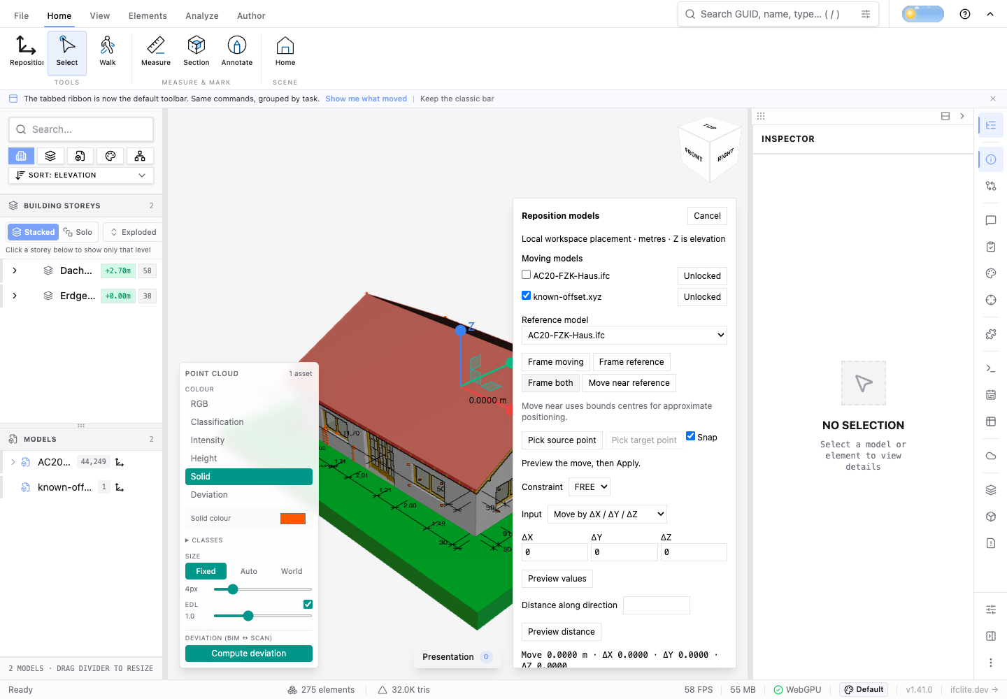
Open Home → Reposition, the model's hierarchy action, or the command palette's Reposition command. IFC models, embedded pointclouds and streamed scans use the same workspace translation. Either upload order is supported. Select one or several moving models and choose a fixed reference model.
- For a large mismatch, use Frame moving, Frame reference or Frame both to locate the data. Move near reference brings the first selected model's bounds centre to the reference centre; it is an approximate preview.
- Pick a source point on the moving model and a target point on the reference. Snapping uses mesh vertices, edges and faces, and actual scan points. The highlighted point and live dimensions show the proposed displacement.
- Refine with X/Y/Z or XY/XZ/YZ constraints, the axis and plane handles, or
typed values. Numbers accept a decimal dot or comma, scientific notation,
and
mm,cm,m,km,inandft; bare numbers mean metres. Workspace coordinates use engineering axes with Z as elevation. - Move by ΔX / ΔY / ΔZ enters a displacement from the committed position. Set source point X / Y / Z sets the picked point's destination in the workspace frame. A signed distance follows the constrained axis or current move direction. Hold Shift during point picking for orthogonal movement. Choose X/Y/Z and use ↑/↓ for the configured nudge increment.
- Apply creates one undo operation for the whole group. Escape or Cancel discards the preview. Enter in a numeric field previews its value; Enter with focus in the viewport applies. Focused buttons keep their normal keyboard activation. Reset placement returns selected models to their automatically aligned positions. Locks prevent starting new moves; undo restores positions without changing subsequent lock settings.
Rotating a model
Rotate turns the selected models about the workspace vertical axis only — the heading change that seats a building on a site. Tilting a model out of plumb is not offered.
- Heading is an absolute angle in degrees, positive counter-clockwise seen
from above, wrapped to (-180°, 180°]. Re-entering it always turns the model
once from its original geometry, so an angle can be edited without
compounding, and
0restores the model exactly. - Pivot X / Y is the workspace point the axis passes through, in metres — one point for every selected model, whatever their translations. It defaults to the model's bounds centre and is shown, never implied; elevation does not affect a vertical-axis turn. Once a model has a heading it keeps the pivot it was given until you change it.
- The rotation is applied to the model before the translation above, so the pivot is stored in each model's own frame and moves with the model when it is moved afterwards. Rotating and then moving is not the same arrangement as moving and then rotating.
- Rotating creates one undo entry for the whole selection on the same stack as moves, and rides Undo placement / Redo placement and Reset placement with them. Locked models refuse to rotate.
- Models with GPU-instanced geometry (repeated elements the viewer draws as
instances, such as doors, windows or columns) rotate too: the instanced
occurrences turn about the same axis as the model's flat geometry, from the
renderer's own instance data. Pointclouds cannot be rotated — they are
renderer handles that carry a translation but no heading. Models still in
pendingorstreaming-geometrywhose kind is not known yet (no geometry, no instanced shard, no pointcloud handle) are refused too, until it is. In both cases the panel says why, a selection containing one is refused as a whole, and a placement manifest that would give such a model a heading is not imported.
Unlike a move, a rotation has no drag preview: it rewrites the model's geometry, which is what keeps rendering, picking, bounds, spatial queries and graphical exports reading one set of coordinates rather than each applying the angle for itself. Large models therefore take a moment to turn.
Manual placement composes with automatic georeference alignment. It does not
edit IfcLocalPlacement, map conversion, source geometry or scan files.
Re-aligning the federation cancels picked anchors, preserves manual translations
as literal workspace vectors, and re-applies model rotations on top of the new
alignment. The RTC convergence described at the top of this page moves a model
into the shared frame without re-running a rotation: a heading and that
translation commute, so the turned geometry is already correct. What does follow
the model is the pivot — it names a workspace point rather than a distance,
so it is re-expressed in the new frame, and the number shown in the panel can
change when a georeferenced model joins the federation. Pointcloud handles
follow the workspace translation but are not rotated. Scaling, CRS conversion
and automatic scan registration are separate operations.
Positions are saved locally by source contents and coordinate frame. Reloading an unambiguous source restores its committed position; previews are never saved. Matching reads every source byte using bounded SHA-256 chunks; renaming a file keeps its identity, while changed contents require a new placement. For streamed scans, matching runs after loading completes so it does not delay the first points. Automatic restore and local saving become available once that background pass finishes; moves made meanwhile are preserved and then saved. Removing the scan stops the pass. Export placements downloads a versioned JSON manifest. Import checks units, axes, frame and source identity before applying the entire group. Repeated copies of one source need explicit instance bindings. Import respects current locks. Placement is local to this browser workspace and is not shared with collaboration peers.
Rendering, selection, snapping, bounds, section geometry and graphical exports use the placed geometry. Existing measurements keep their recorded workspace points and are labelled Stale after movement; remeasure them. Clash and scan deviation results are invalidated and must be recomputed after applying a move. Cancelling a preview restores prior measurement validity and analysis results; a deviation result whose GPU buffers were overwritten during the preview must be recomputed. Source-model comparison still describes authored changes rather than registration offsets. STEP IFC exports retain authored coordinates; graphical GLB and IFC5 geometry exports include workspace placement. Export the placement manifest alongside source IFC or scan files when sharing this arrangement. Transformed LAS/E57 writing is not provided.
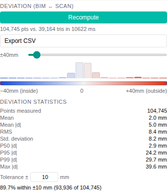
After a completed deviation run, the Deviation panel reads every computed point's signed distance back once and shows summary statistics: points measured, signed mean, mean and RMS of |d|, standard deviation, P50, P95, P99 and maximum of |d|, and the share of points within an editable tolerance (10 mm by default). A histogram above the colour legend counts points over the same range as the ramp, with each bar in its ramp colour; points outside the range are counted below it. Points the compute pass clamped at its 1 m limit are counted separately, because their true distance is larger. Percentiles are exact nearest-rank values of |d|, not estimates, found by a radix select over the readback without copying it. Every figure takes at most two linear passes, run in short slices so the viewer stays responsive at the 25-million-point cap. The readback holds 4 bytes per point in memory until the next run or until the result is invalidated. A streamed COPC scan keeps only the octree nodes the view needs, so its statistics and CSV describe the points resident now: when the view adds or drops nodes, including when the scan leaves the view entirely, deviation re-runs and the statistics are read back again.
The panel's Export CSV action writes the same statistics for each scan
asset, in metres, with the tolerance used. With several scan assets, a final
row pools all of their points. Each scan row names the scan's own model, its
GlobalId, Name and IFC class, resolved from the asset's federated id, so the
attribution holds in any load order and after other models are removed; the
Model column appears when several models are loaded. The renderer's
readDeviationDistances() method returns the signed distances grouped by scan
asset, and readDeviationAssetStats() returns per-asset statistics; both read
GPU deviation buffers only when called and report nothing for a scan asset
added after the run. Each asset carries the expressId and modelIndex it was
uploaded or bound with: the viewer binds a streamed scan to both through
relabelPointCloudAsset(handle, expressId, modelIndex) once its model is
registered. Recompute before exporting after a model change.
import { computeDeviationStatisticsAsync, type Renderer } from '@ifc-lite/renderer';

declare const renderer: Renderer;
const { values } = await renderer.readDeviationDistances();
// Sliced so the page keeps painting; `computeDeviationStatistics` is the
// synchronous form for a worker, the CLI or a test.
const stats = await computeDeviationStatisticsAsync(values, { tolerance: 0.01, clipRange: 1 });
console.log(stats.p95Abs, stats.withinTolerance?.share, stats.clippedCount);
Scan to BIM: detect and review elements
The Point Clouds panel's Scan to BIM section runs Detect elements on a
loaded scan. It reads the scan's retained sample (up to 2 million points, or
the coarse COPC levels). When the section box is on and shown, it reads only
the points inside the box, mapped back through the scan's alignment. Planes and
cylinders are found off the main thread and turned into proposed IfcWall,
IfcSlab, IfcColumn and pipe elements in the coordinates of the active IFC
model, or the first one loaded. The proposals include that model's offsets,
its placement and the scan's alignment. Pipes are IfcPipeSegment, or
IfcFlowSegment in an IFC2X3 model. With no IFC model loaded, proposals use
the workspace coordinates. Cancel stops a running detection, and a second
Detect replaces it. The rules behind the proposals (wall pairing, default
thicknesses, floor and ceiling sides, snapping, confidence) are in the
proposal contract.
The detected planes and cylinders are drawn over the scan, coloured by proposed class: walls blue, slabs grey, columns orange, pipes green. The review list shows each proposal's size, how it was derived, its confidence and its fit (RMS and points). Accept or Reject each one, or use Accept all shown and Reject all shown after filtering by class and minimum confidence. Rejected proposals disappear from the overlay, and accepted ones are drawn more opaque. A run ends when its scan or its IFC model is removed; removing either while detection runs stops the worker and discards its result.
Create accepted elements writes the accepted proposals into the IFC
model as one undo step, through the same path as the Model workspace's own
commands. The new elements appear in the model tree and the properties
panel, and they export with the model. Each element goes on the highest
storey whose floor is at or below its base, within 0.3 m; an element below
every floor goes on the lowest storey. Its geometry passes through that
storey's own frame:
- walls have a centred axis;
- slabs are the outline extruded by their thickness;
- columns have a circular profile;
- pipes are a circular member along the axis, reclassified as
IfcPipeSegment or IfcFlowSegment.
Each element carries an IfcLite_ScanDetection property set with
SourceScan, DetectionId, Basis, SourceDetections, Confidence,
FitRmsMetres and InlierPoints. The set does not use the Pset_ prefix,
which is reserved for buildingSMART's own property sets.
- Create acts on the accepted proposals the filter shows. Accepted proposals the filter hides are counted under the button, not created.
- Created proposals are marked Created while the target model holds an element with their GlobalId, so a reopened export still shows them. Undoing the batch makes them available to create again.
- Detect again starts a fresh review. If the target model already holds elements created from the same scan earlier in the session, the bar warns that creating again may duplicate them. It does not match new proposals to old elements, and it does not know about elements created in an earlier session.
- Create refuses when the scan's placement or alignment, or the workspace anchor, has changed since detection: detect again first.
Editing must be on. With no IFC model loaded, Create a blank IFC model adds one beside the scan to hold the elements.
World Context refreshes its Cesium model after movement pauses, using the same placed geometry. Its previous model stays visible until the replacement is ready; the WebGPU view updates immediately throughout the move.
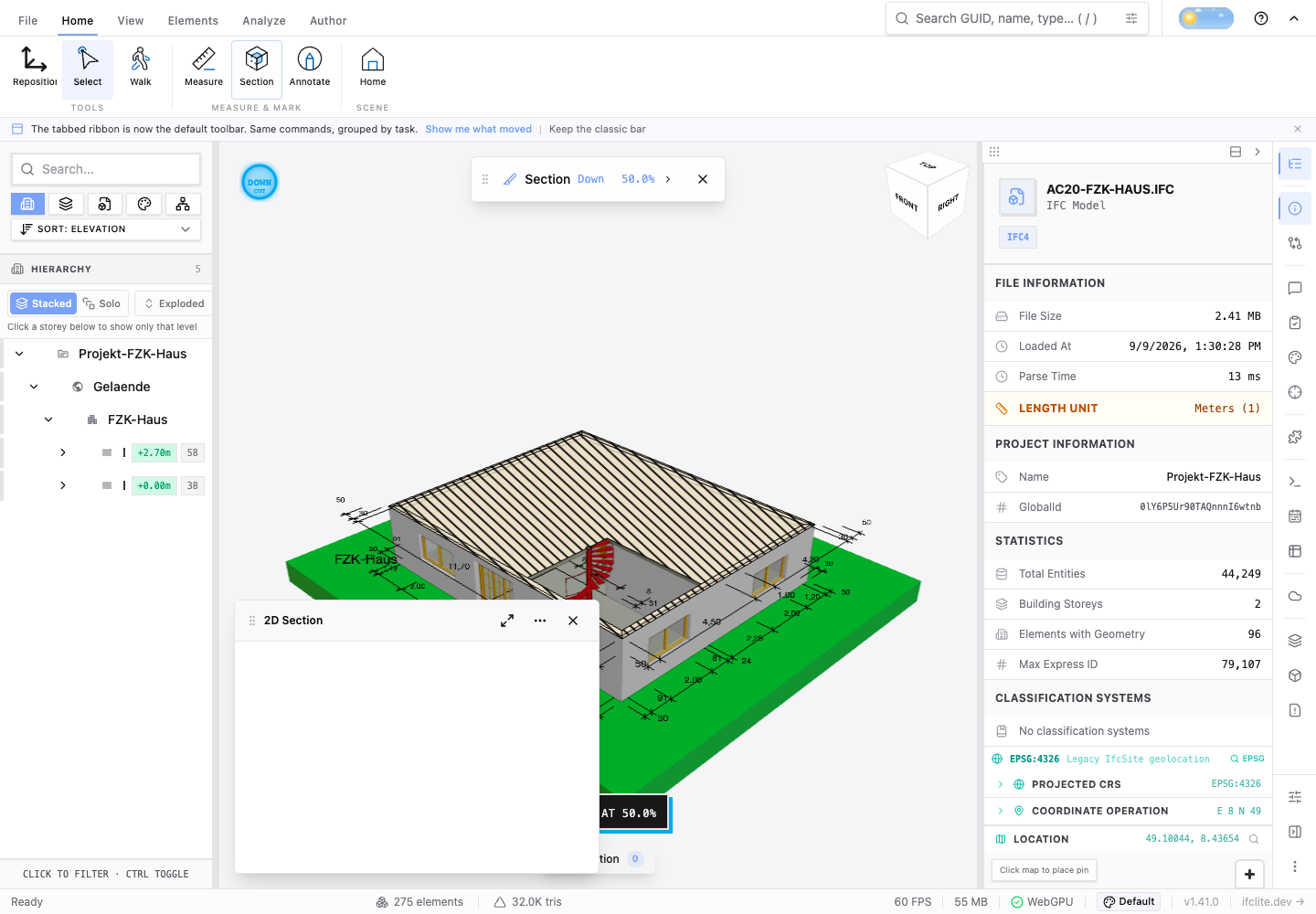
Both the 3D cut and the 2D drawing resolve section percentages from the same placed bounds, including a model moved beyond its original extent. Construction projection also uses the placed floor elevations. Moving a model and its section plane together preserves the floor/ceiling projection bands and the resulting drawing geometry, for either section direction. Floor bands refresh when the model moves or its storey membership changes; no reload is needed. See 2D drawings after repositioning.
Large translations and their subsequent fine corrections are retained in double precision. Mesh and scan vertices stay near their own decode/draw origins; manual correction is composed before GPU narrowing. Precision still depends on the source data, a scan's spatial extent and the final distance from the render origin. Bring distant data near the reference before millimetre adjustment; repositioning cannot recover detail already rounded in the source file.
Merging to a Single File (CLI)
In-viewer federation keeps each model as a separate file with an ID offset. When
you instead want to bake several models into one physical IFC file, use the
ifc-lite merge command:
Pass two or more input files (positional args) and one --out target. The
spatial hierarchy (sites, buildings, storeys) is unified by name and elevation by
default so the merged file has one coherent tree rather than duplicated
containers.
| Flag | Values | Default | Effect |
|---|---|---|---|
--out <file> |
path | required | Output file path |
--schema |
IFC2X3 / IFC4 / IFC4X3 |
IFC4 |
Output schema version |
--unit-reconciliation |
auto / normalize / assume-shared |
auto |
How to handle models whose length unit differs from the first file. auto federates them as separate projects; normalize rescales them into the first file's unit; assume-shared forces one project without rescaling |
--merge-sites |
single / by-name |
combined heuristic | How IfcSite records are matched across models |
--merge-buildings |
single / by-name |
combined heuristic | How IfcBuilding records are matched |
--merge-storeys |
by-name / by-elevation / by-name-then-elevation |
combined heuristic | How IfcBuildingStorey records are matched |
--drop-empty-containers |
flag | off | Leave out sites, buildings, storeys and spaces the merged model leaves holding nothing (the "Merge Projects" recipe step matching alone does not cover) |
--json |
flag | off | Emit machine-readable stats (entity counts, warnings) to stdout |
FederatedModel Type
Each loaded model is tracked as a FederatedModel:
interface FederatedModel {
  id: string;            // Unique model identifier
  name: string;          // Display name
  idOffset: number;      // Global ID offset
  maxExpressId: number;  // Highest expressId in this model
  visible: boolean;      // Visibility state
  collapsed: boolean;    // Hierarchy tree state
}
Performance Considerations
- Each model adds its entities to the shared spatial index and renderer
- Memory usage scales linearly with total entity count across all models
- The FederationRegistry resolves IDs in O(1) local->global, O(log N) global->local
- Visibility toggling per-model is O(1) (GPU-level filtering)
- Loading 5+ large models (100MB+ each) may require the server paradigm for best performance
IFC5 Federated Layers
For IFC5 (IFCX) files, federation works differently - files can be loaded as overlay layers where later files override properties from earlier ones:
import { parseFederatedIfcx } from '@ifc-lite/ifcx';

const result = await parseFederatedIfcx([
  { buffer: baseBuffer, name: 'base-model.ifcx' },
  { buffer: overlayBuffer, name: 'add-fire-rating.ifcx' },
]);

// Properties from the overlay take precedence
// Wall now has FireRating property from the overlay file
See the IFC5 Parsing Guide for more details on IFCX format support.
Filename tags in saved workflows
Session automation loads models through the same federation loader and can assign model tags from their original filenames. All matching rules union their tag names, preserving manual tags. Checks target qualified file slots, exact filenames or normalized tag names. Duplicate filenames require explicit slot bindings; comparison A/base and B/head roles must each resolve exactly one model.